Let's Clone a Cloner - Part 3: Putting It All Together

Table of contents
We have arrived at our final stage of metamorphosis, taking our pupa and morphing it into a hacking machine. Let's finish this journey.

In the first blog, we took various MaxiProx builds and attempted to build one for ourselves, dipping our toes into the hardware hacking pond. In the second blog, we had to redesign our initial build to fix some power issues to get the range that we were expecting. In this final blog, we will neatly package up all the components into a mobile MaxiProx, test it out, and make a few more adjustments, if needed.
Laying Out the New Parts
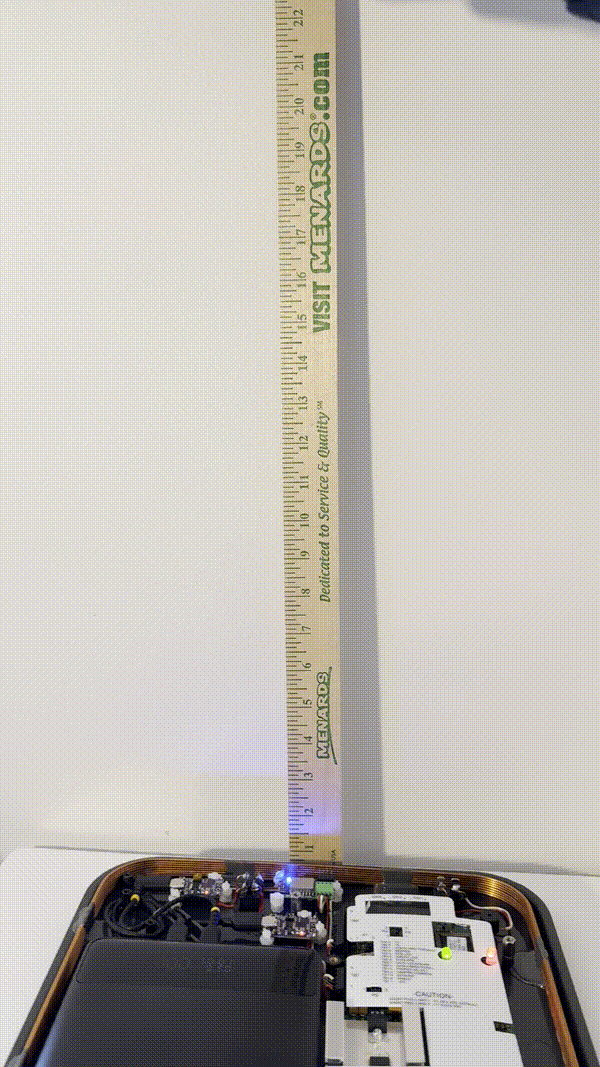
As this battery pack is much larger, I must rethink how I am going to internally arrange the components within the MaxiProx. One thing to note is that since the ESP RFID Tool is going to be powered from a separate USB port, I don’t need the Power Buck module, so I took that out and replaced it with the spare PD trigger that I had. This way, when I do place the battery in the MaxiProx, it will all fit.
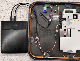
With all of the components in the MaxiProx, it will look something like this:
Installing the Beeper (Speaker) Switch
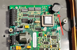
Before I mark where all the components will go, I want to circle back to the little beeper, or speaker, that I want to control with an on/off switch. The main reason for the kill switch is not to enable the beeper for testing, but to ensure that the beeper is off during an assessment. The first step is to remove the logic board from the MaxiProx so we can access the soldering points needed.
I will be soldering, so I need to think about safety. Always remember that solder fumes can be dangerous, so make sure that there is plenty of ventilation or make sure you are in a large room. There is also the possibility of lead being in the solder or components that you are working with, so wherever you are soldering be sure to clean up after yourself and make sure you are not in a place where food is prepared or consumed. Lastly, the solder tip will reach temperatures between 300 to 600 degrees Fahrenheit, so be careful of the tip. Also, safety glasses are recommended.
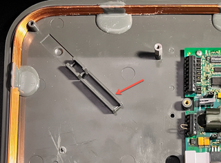
At the bottom of the logic board, there are two connections for the antennae. These will need to be unsoldered. This can be done by heating up the solder and using a desoldering wick or a desolder pump.
The beeper is at the very top-right of the logic board. Here, I have it covered in electrical tape to mute the sound during my testing.
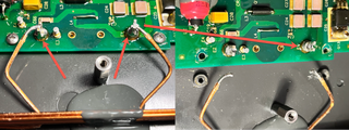
When you flip the board over, you will see that the beeper is soldered onto the board with two leads, a positive and a negative. You will need to heat up the solder and remove it. Now, to solder it back on, you will only solder one lead back on and the other lead will hang off the board. Place the negative lead into the board and solder it back on while leaving the positive lead hanging off the board.
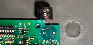
To install the switch, we need to first run some wire to the beeper. For this I chose to go with red and white wire. Solder the white wire to the negative lead of the beeper and the red wire to the logic board, which will later be connected to the switch. Once this is done, we can attach the mainboard back onto the shell and resolder the antennae.
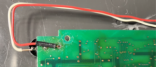
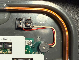
For the switch, I cut a hole in the shell of the MaxiProx near the beeper and soldered the wires I added to the switch.
You might be asking yourself “What if you accidentally flip the switch on during an assessment?” To account for that, I decided to install a switch cover to make sure that I don’t accidentally hit it and enable the beeper. The problem is that I could not find one I wanted that fits the specifications of my switch. However, I did find a cover for a round push-button style switch that I could make work, but I would need to modify it. Being careful not to break it, I did this with a coping saw, utility knife, and a file.
Part | Retailer | Cost |
Mouser | $3.66 |
Securing the Battery
The battery pack is a little too big to fit into the MaxiProx without some modification. There is a large bump out channel in the top-left that will need to be trimmed.
As the battery barely fits in the MaxiProx, modifications will need to be made to both make it fit and also secure it from moving around freely within the case once everything is put back together. I decided to have the battery sit flush on the standoff post at the bottom of the MaxiProx and cut this bump out channel to be flush with the top of the battery so that it fits snug. Additionally, I will need to carve out spots for the USB-C cables that plug into the battery. I found that this is a good thing because it will help anchor the battery pack in place.
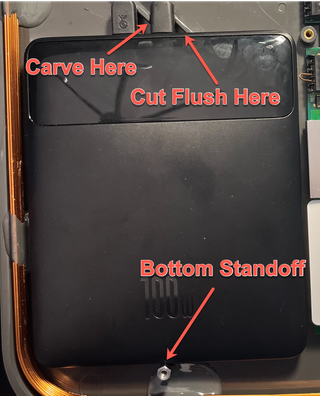
Since I already had all the components out and was making modifications, I also carved out a hole for the power switch. To do this, I made a stencil out of paper and marked the rectangle. Cutting this out was a pain as I had to use two different drill bits. The first bit was used to make small holes for the corners, then the larger one to fit a coping saw blade to cut it by hand. Initially, I tried to use a Dremel, but the saw blade was too large to go through the thick plastic. Also, it ended up just melting the plastic and not cutting into it.
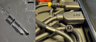
Here is a side-by-side image of the modification I made. On the left is the modified channel and the speaker switch hole, and on the right is with the battery installed and the USB-C cables in the cutouts.
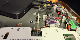
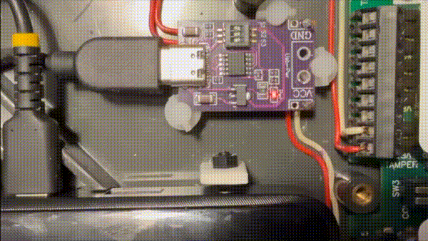
Securing the ESP RFID Tool and PD Triggers
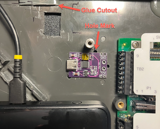
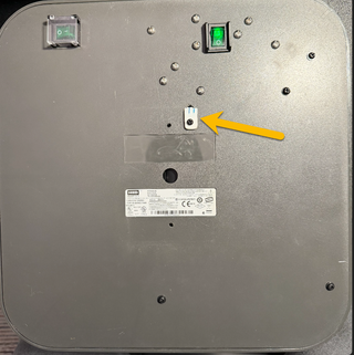
To add the board edge mount standoffs, I placed the ESP RFID Tool and PD triggers where I wanted them and marked a dot where I wanted the standoff holes to be. I had to place the holes in a spot on the board that did not have a component. Due to the size of the boards and where the components were, I could only use three standoffs as opposed to a standoff on each corner of the board. I then drilled through the board so that the standoff could be screwed in. There was a spot where I had to cut out the antennae glue to install the PD trigger and the on/off switch.
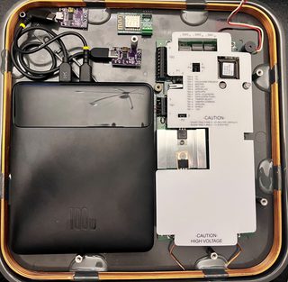
Final Component Layout
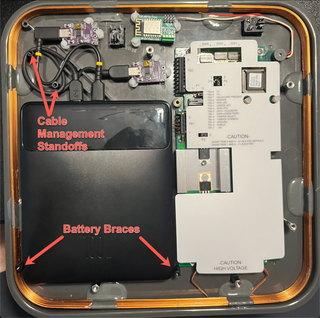
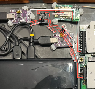
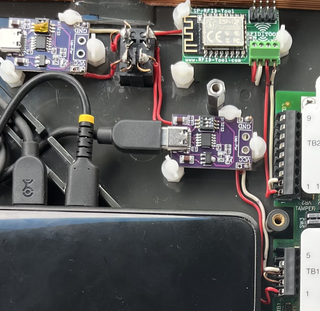
What does it all look like? Here is the final result…The battery is held in place at the top with the cutouts to hold the USB-C cables and bottom by the existing standoff to stop it from going up and down. The top will stop the battery from going left to right. But there is nothing to support it at the bottom, so to fix that, I added some more standoffs. And while I was at it, I also added some standoffs at the top-left for some USB-C cable management.
Final Setup
To hardwire everything in, I will need to get back to soldering. But first, let’s draw up a schematic. One thing to note is the switches I purchased have their own internal LED that can be used to illuminate the switch when flipped on. Because of this, you need to take extra care with how you insert the switch into your circuit. The LED has its own separate internal circuit that is exposed via two of the four external connections on the bottom of the switch. In order to better understand how this works and how it needs to be wired, we need to break down what kind of switch this is and how it works.
The switch I have is a Double Pole Single Throw (DPST). This means the switch can simultaneously control two separate circuits (Double Pole) with each circuit having only two states, ON and OFF. This type of switch is useful for situations where you want to toggle the switch between its two states, ON and OFF, and have two separate circuits connect. In my case, the two circuits I’m controlling are supplying power to both the MaxiProx and the ESP RFID Tool.
To configure the DPST switch so we can turn on both the MaxiProx and the ESP RFID Tool at the same time, I need to connect the positive lines from the two PD triggers to the positive connectors on the switch. The other side of the pole will go to the respective PD trigger. This way when the switch is turned off, power is cut from the PD trigger to the devices. Here is the layout that I was thinking of and the final result (and yes, I know that my soldering is not on point).
Pupa Range Test
Just for good housekeeping, let's give it one final range test. I had tested it with and without the cover and both ended up with a range from 15” to 19”. From the first test with the 100W battery, I lost 2" to 6" of range. I think I can attribute this to the possible placement of the components and extra metal screws, but overall, not that bad. However, I will have to keep this in mind when I am in the field during an actual assessment.
Results (and Failures) of Live Testing
Part 2 of my blog series was published a year ago. I wanted to test this out successfully before posting the final blog in this grouping, but every physical assessment that I took this on for TrustedSec failed to clone a card. The reason, thankfully, is that every client I tested was using High-Frequency (HF) proximity cards. If you don't know the difference, then I have to apologize as you have made it to the end of my 3-part blog series and I never explained the difference between Low-Frequency (LF) and HF.
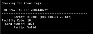
LF cards consist of three sets of numbers that are used for access: the TAG ID, Facility Code, and card number. If you have these, then you can either replay it (spoof the card by broadcasting it via a separate device) or write it to a card and gain access to doors in the context of the original badge.
On the other hand, HF cards apply various encryption, encoding, and/or challenges that are not found in LF cards. There are various types of LF cards, but they all function in the same way. They will transmit plaintext numbers, and if you can read those numbers, you can replay them to gain access into a controlled door. Cloning HF cards, however, requires you to decrypt/decode the keys and possibly attempt to apply a challenge-response mechanism that protects against replay attacks.

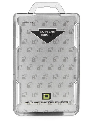
While on an assessment, I noticed the client had deployed a control that I have not seen before but was effective. The client invested in RFID badge holders that shielded the cards from cloning attacks. The specific product that they used was from ID Stronghold.
Speaking of Shielding - Does it Work?

You might remember that I previously purchased some Faraday fabric for this project.
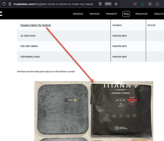
There were two thoughts behind this purchase. The first was to see if I could shield the RFID Cloner from other metal tools that I carry or even the material of the bag that is going to carry the cloner such as zippers and buckles. The second was to test the effectiveness of the Faraday fabric by shielding a badge.
To test how the Faraday fabric affects the MaxiProx, I ran one test (the left video) with the fabric laying to the left of the MaxiProx and a second test (the right video) with the fabric laid out underneath, simulating if I could line my carrying bag and shield my tools, thus reducing interference. The left video, without the Faraday fabric underneath, gave me the normal range of 18" while the right video, with the Faraday fabric underneath, reduced the range to 6".
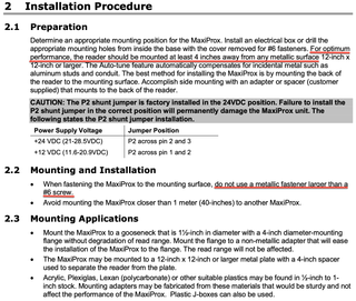
If you are wondering why the range is affected by placing Faraday fabric behind the MaxiProx, then it is time to understand how RFID works. The MaxiProx Installation manual specifically states not to have metal within a certain range of the reader.
RFID signals are electromagnetic, so having metal in proximity of the signal will affect the electromagnetic signal. This is true with any wireless signal. Most of you reading this may know that when you are indoors and surrounded by all types of metal, your wireless Internet or cellular signal will be degraded. This is also true with RFID. So, I must be careful with what I have around my MaxiProx when I plan on using it. This includes metal tools, bag zippers and/or satchel buckles, belts, door loids, etc. The more I use this cloner, the more I might tinker and test out various implementations of the Faraday fabric and placements of the cloner to see if I can somehow amplify the signal.
An additional test I performed was to see if shielding the RFID card would stop someone from reading the card. I started with just one layer of the Faraday fabric and continued to increase the layers. Here are the results of that test:
Faraday Fabric Layer | Read Distance (Inches) |
18" | |
1 | 13" |
2 | 11" |
3 | 9" |
4 | 7" |
I was a little shocked to see I needed multiple layers to effectively shield the RFID card. This makes me question all those RFID blocking sleeves and bags. I circled back, looking at the product that I purchased, and found this:

Final R&D
I did come across an issue with my build while using it in the field. Everything works as it should even though I did not get a successful clone. However, if I turn off the switch that controls the power to the ESP RFID Key and the MaxiProx, eventually the battery would go to sleep. Turning the switch back on wouldn’t trigger the PD trigger to wake the battery. This is because the switch is between the PD trigger and the ESP RFID Tool and this does not turn on the PD trigger.
One solution would be to splice a USB-C cable and put the switch in between the battery and the PD trigger. That said, I am not going to split open one of my USB-C cables to put the switch in line with the battery and PD trigger.
Another option is to activate the wake button on the battery that is next to the USB ports. I installed the switch so when I was walking through common spaces or between locations, I wouldn’t be cloning unnecessary badges. It also allowed me to preserve the battery life.
I stewed on this for quite a while trying to come up with a solution. What I finally came up with was to create a slider switch to activate the power switch on the battery.
I could not find any suitable material I could modify to make a sliding switch, so I started thinking of possibly 3D printing one. Since I don't have a 3D printer, I reached out to my good friend and colleague Justin Bollinger who has a 3D printer and a plethora of knowledge. However, he confirmed something I was already thinking, which is a print that small with the tolerances that are required would probably take too long and would require lots of trial and error. But if I owned a 3D printer, I would probably go down that route.
Justin did bring up another good point, which is that I could introduce some sort of constant power drain such as an LED light or a USB Bluetooth adapter. However, given that I don't have much room left in the MaxiProx, a USB adapter to drain power wouldn’t really work. Plus, I don't want to introduce any more components that could cause any additional interference.
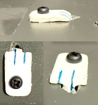
So, I was back to looking for a suitable material that I could modify but still coming up blank. Until one day, I was in my junk drawer and found a large collection of the old phone chargers. I decided to gut one and use the plastic shell since it was thick and durable and had a nice radius to the corner to provide strength to the L-shape.
I took the L-shape plastic piece that I had and ended up cutting channels in the bottom of the L like an I-beam so that it could sandwich the MaxiProx shell. This way it would be able to slide back and forth and be held in place. Here is the rear of the MaxiProx after adding the slider:
Additionally, below are various close-up pictures of the switch on the outside. It’s not pretty, and cutting a piece this small by hand was difficult.
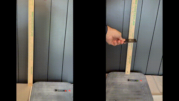
To activate the battery wake button, I added a nylon standoff screw on the vertical part of the L. To make sure it stayed in line with the battery button, I created a channel in the MaxiProx shell to have a second nylon screw slide back and forth. You can see the bottom part of the screw in the image above.
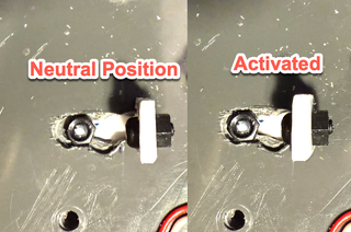
Here is the switch in action. One thing to note: there is no spring to bring back the button to the neutral position, but that's okay. The switch does nothing other than wake the battery, so if it is constantly depressed, nothing happens.
Final Wrap-Up and Bill of Materials
To give you an idea of what it would cost to build your own device like this, here is what I paid. Fine print disclaimer in normal print —This is what I paid at the time of my purchase. The prices do not include taxes and shipping. Shipping was quite large for some items but free for others.
Item | Part | Quantity | Retailer | What I Paid |
HID MaxiProx | HID MaxiProx 5375 | 1 | eBay (Used) | $160.00 |
Battery | 1 | Amazon | $64.99 | |
ESP RFID Tool | 1 | Hacker Warehouse | $30.00 | |
PD Trigger | 1 | Amazon | $9.99 | |
Switch | mxuteuk 5pcs AC110/120V Lighted Rocker Switch DPST (KCD1-4-201NG) | 1 | Amazon | $7.99 |
Switch Barrier | 1 | Mouser | $1.67 | |
Switch Protective Guard | 1 | Mouser | $3.08 | |
Chip Mount | 3 | Mouser | $2.90 | |
Board Standoffs | 1 | Amazon | $9.00 | |
Cable | 20 AWG Wire | 1 | Had this item | - |
USB Cable | Cable Matters 3-Pack USB C Charging Cable 1ft (201402-BLK-1x3) | 1 | Amazon | $8.99 |
MaxiProx Screw | 1 | Amazon | $7.69 | |
Right Angle USB Cable | StarTech.com 6” Right Angle USB-C Cable (R2CCR-15C-USB-CABLE) | 1 | Amazon | $14.05 |
Not including taxes and shipping, this came out to a total of $320.35 and some of your time. This journey was a lot of fun, and I’m happy that I could share it with you. There were things that I learned along the way and I hope you learned a few things as well. I encourage you to hack away (with permission, of course) to make things better and more secure!