Let’s Clone a Cloner...To Meet My Needs

It was my second Physical Penetration Test here at TrustedSec and I was paired with colleague Paul Burkeland. After arriving at the hotel, Paul stated that he needed 16 AA batteries, so we went to the local CVS. I was floored at not only the need to buy 16 AA batteries but also the cost for 16 AA batteries at CVS!
The batteries were needed for a 12-inch by 12-inch long-range Radio Frequency Identification (RFID) card reader (such as the ones you find in a parking garage used to raise a boom or open a gate after you 'badge in'). These types of long-range readers can read a passive, one-way tag from up to two feet away. I was astounded at what Paul showed me. This was a homebuilt reader running off an Arduino card that had an LCD screen. It was a mobile badge cloner built by TrustedSec’s own Jason Ashton.
Many years later, I ended up getting myself a Proxmark3 RDV4 to clone badges. Anyone who has a Proxmark knows that you figuratively have to touch the badge that you are cloning for it to work. I have always aspired to build my own 12-inch by 12-inch badge cloner. Now that day has finally come. Bear with me, as I have never built anything quite like this before. I welcome you to follow along my journey as I tackle this new puzzle. And perhaps my trials and tribulations will teach you something new as well.
Background
To be clear, I am not an electrical engineer or a hardware hacker. But, I love puzzles, fixing things, and learning new skills, just like most of you reading this probably do. My first experience as a ‘sparky’ came at the age of 10, when my electrician uncle bought me a multimeter and some other basic tools. He showed me how to use them, how to handle electricity safely, and some ‘dos and do nots’. At the age of 14, I remodeled my parents' basement, electrical and all, with the help of my parents' friend. You could say that back then, this was the original YouTube.
Fast-forwarding to modern times, I have had some electronics that fell victim to the mid-2000s capacitor plague. I was able to replace the bad capacitors on my TV and my stereo system and extend their lives for 10 years. I did all this thanks to the early and current versions of 'YouTube'.
Like many, I am a self-taught electrical handyman, so hopefully, I don't earn the Darwin Electrical Engineering Championship Ring:

To Build…You Need a Plan, a Foundation, and Material
What cloner are we cloning, and what are my needs? I found a post from Shain Lakin on phrack.me that is a cloned version of Bishop Fox’s Tastic RFID Thief. This seemed like a simple build, as Shain’s write-up was very thorough. It also was built with an ESP RFID Tool that includes built-in Wi-Fi and a web browser to covertly check if you have cloned a badge. And the best part? It uses rechargeable 18650 batteries so you don’t have to pay an arm and a leg for 16 AA batteries.
Shortly after finding Shain’s build, I spoke with Jason Ashton about my thoughts on building my own cloner. Jason’s response? “Oh, I fully documented my build in a blog that you should take a look at.” I let Jason know about finding Shain’s blog and how easy of a build it seemed. After all, take a look at the list of parts needed for each build. Jason’s build from 2018 is on the left, and Shain’s from 2022 is on the right.
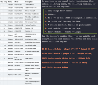
I had some ideas for my build and wanted to consult with Jason. My ‘wish list’ for the build included the following:
- A USB power bank instead of rechargeable batteries
- Using two USB ports—one to power the MaxiProx and another to power the ESP RFID Tool
- Cutting a USB cable for power from the power bank to the MaxiProx and ESP RFID Tool
- Jason's sound switch to manually turn the speaker on or off
Jason’s first concern was the USB power bank and if it could supply enough power. Shain’s build used a PowerBoost module that increased the 5-volt input from the batteries to the 12 volts that the HID MaxiProx requires. My thoughts were that I could use one of the three USB ports on the power bank for the ESP RFID Tool and another to power the HID MaxiProx. Jason had no objection but was concerned about successfully dissecting the USB cable and pulling 12 volts over the wires. We were both hesitant on splitting the USB cable and connecting it to the ESP RFID Tool and the HID MaxiProx.
The Plan
With the plan set, I was off to order the parts. Here is the first round of parts I ordered (with hyperlinks and the price paid at the time of purchase):
Part | Retailer | Cost |
HID MaxiProx 5375 | eBay (Used) | $160.00 ea |
DFRobot | $7.50 | |
DFRobot | $7.50 | |
Hacker Warehouse | $30.00 | |
Mouser | $7.43 | |
Mouser | $2.90 | |
Mouser | $0.33 ea | |
Mouser | $0.36 ea | |
Amazon | $12.00 | |
Amazon | $23.00 | |
20 AWG Wire | Had this item |
|
Old USB Cables | Had this item |
|
USB Battery Pack | Had this item |
|
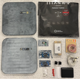
And here are the initial parts laid out on the kitchen counter:
As excited as I was to get this project underway, I knew I wanted to share this endeavor with others, to have extra sets of eyes on my process. Off to tell the TrustedSec Hardware Hacking team—my yellow brick road, so to speak.

I have to tell you—they were like kids in a candy shop and immediately started asking all the right questions as I stumbled on my requests:
- What model of the MaxiProx are you using?
- What are the MaxiProx power requirements?
- What are the specs of the USB battery pack?
- How will the power be supplied?
- Have you calculated the required Watt-hours (Wh) needed?
Power Requirements, Change of Power Source, and More Shopping
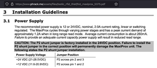
According to the power specifications of the MaxiProx, the power requirement during peak operation is 12 volts at 1.2 amps. The recommended power requirement for the power supply is 12 volts at 2 amps.
Now armed with the power requirements, I needed to know what power was being supplied from the USB battery pack. The first pack I used was an Anker PowerCore 13000. The Anker has two USB-A ports that each supply 5 volts at 3 amps.
I could use the boost module, but I also had another USB battery pack with a USB-C PD (Power Delivery) port. USB ports that are PD-capable allow communication between the device that needs charging and the power source. The device that needs charging communicates to the power source what power requirements are needed. The power source then supplies the specific power that is required to the device that needs charging.
The battery pack with USB-C PD is nice because the one port supplies the required 12 volts at 1.5 amps. It will also charge quickly over that same USB-C port, and as a bonus, the height fits in the MaxiProx.


The TrustedSec Hardware Hacking team brought to my attention a USB-PD trigger board. The USB-PD trigger will request a certain voltage of the PD power supply. The good thing about this board is that there is no need to dissect a USB cable to connect into the MaxiProx. Additionally, I can supply the required 12 volts to the MaxiProx with no issues and no need to have the boost module.
So, back to ordering more parts. What I ended up ordering was a 12-inch long USB-C to USB-C cable (due to finding a good price, I actually ordered a three-pack), a two-pack of PD triggers, and a 5/8-inch long #6-32 thumb screw. The thumb screw allows for the ability to open and close the MaxiProx without the use of a screwdriver.
Part | Retailer | Cost |
Amazon | $8.99 | |
Amazon | $9.99 | |
Amazon | $7.69 |

The Build, The Test, The Frustration
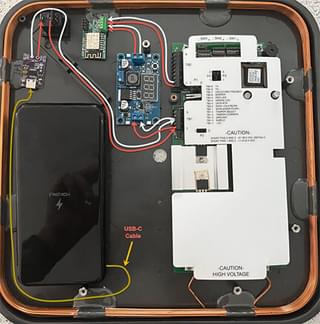
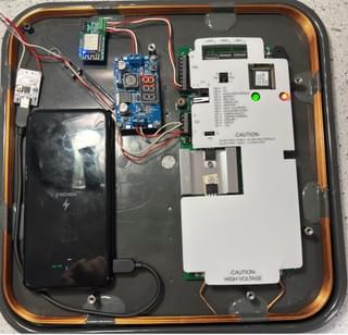
So, I have a plan, I have my parts, and I am feeling eager and ready. Let’s put it all together. First, I lay out where everything is going to go:

This looks good, and it all fits. Now, it's time to worry about how the cables are going to be routed. There is a channel just above the battery pack and below the ESP RFID Tool that sits to the right of the USB PD trigger board. I plan to run the wires from the USB PD trigger board to the switch and then down that channel.
This schematic is the initial layout of the wires:
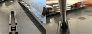
To route the wires through the channel, I first must tunnel out the bottom part of the channel. I could have done this with a Dremel or an oscillating multi-tool, but I decided to perform this by hand with a hacksaw blade and a pair of needle-nose pliers.
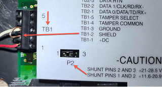
Time to wire it up!!! There are three things that needed to be done before I could power it up. First and most importantly, I need to make sure that the MaxiProx is configured for 12V and not 24V as stated in the figure “HID MaxiProx Power Requirements.” On the MaxiProx, there is a jumper right next to the terminal block (TB1) that the power plugs into. Connecting P1 and P2 supply 12V and connecting P2 and P3 supply 24V. Since we need 12V, we need to hand P1 and P2 connected with the jumper. Now, another thing that I added was a looped wire to connect the ground to the shield.
Second, the PD trigger needed to be configured to the right voltage. (There were some PD triggers that needed to have some solder points connected to get the desired voltage, but I opted for the board that has DIP switches.)
The bottom of the board had the matrix to configure the DIP switches to achieve the desired voltage. Since I needed 12 volts, I had to configure the DIP switches to have Switch 1 (S1) on, Switch 2 (S2) off, and Switch 3 (S3) on.

And, as always, double-check your setup before you plug it in. If you have never used a multimeter, here is another video from Aftotechmods that is a good, quick, four minutes and 30 seconds that covers everything you need to know.
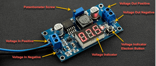
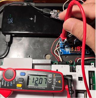
And third, the Power Buck module needs to be configured to allow the appropriate voltage to the ESP RFID Tool. As Shain’s build set the Power Buck module to be 5 volts, I'm doing the same. I purchased a variation of a PowerBoost module that has an onboard voltage indicator. This indicator can be toggled with a black push button next to the screen to view input voltage and output voltage. The first step is to find the wire terminals labeled VIN+ and VIN- to the PD boost module to supply power to the Power Buck module. Make sure to not wire anything to the VOUT terminals yet. Also, the voltage going out must be configured before connecting the ESP RFID Tool.
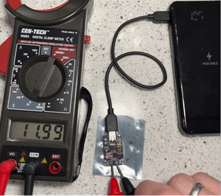
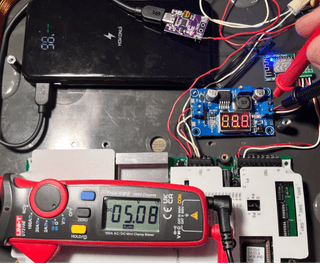
Once I supply power, the onboard voltage indicator will show the voltage registered going into the board. To view the voltage going out of the board, press the voltage indicator button once. Now, set the voltage to 5 volts as Shain did by turning the potentiometer screw counterclockwise. Once that is set, it can be wired up to the ESP RFID Tool.
Before I plugged in my ESP RFID Tool, I verified that the voltage going into the Power Buck Module was correct, and I set the voltage going out. I did confirm this before I wired it up even though the picture does not show it.
For now, I am going to temporarily hardwire everything except the switch, just to see if it all works.
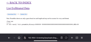
So, it is on, and now I’m off to test if it will read a card. And it does…kind of. Does it read the card? Yes. Checking the ESP RFID Tool logs with a test RFID card shows that it worked.
However, does it give me the long range? Absolutely not. In order for the MaxiProx to read the card, or any card for that matter, the card still needs to be in extremely close proximity to the antennae. Nevertheless, it is working, to an extent. So, what is the problem? Is it the used, sun-faded MaxiProx? Does it have a bad chip or capacitor in it? Maybe the firmware? Possibly an incorrect amount of power being supplied? Is something interfering with the wireless signal, such as the USB battery pack or the placement of the ESP RFID Tool?
At this point, who knows? But, we will find out! To complete this project, I need to figure out the MaxiProx range issue and still tie in the switch, mount all the boards, secure the battery, and install the sound switch. So, keep an eye out for the follow-up blog (or blogs, possibly). Talk to you soon, and go out there and safely hack some hardware!
Shout-Outs and Thank Yous

To be loved is a wonderful thing, and I wanted to send a shout-out to those who have helped me along the way. Just know that the impact of your goodwill is not over yet. And, as this project is not finished, the list is sure to grow. For now, thank you, Jason Ashton, the original TrustedSec electrical hacking pioneer. Also, thank you, TrustedSec Hardware Hacking team members who helped me (Rob Simon, Philip DuBois, Robert Lee, and Dennis Shannon) in my time of need without being too rough on me.