Let’s Clone a Cloner - Part 2: You Have No Power Here

Table of contents
- Could it be Power?
- Sidestep - Understanding Electricity
- Creating More Power
- Understanding a Series Connection
- Understanding a Parallel Connection
- Understanding a Series/Parallel Connection
- Testing a Series Connection
- Testing a Series/Parallel Connection
- Pinpointing the Problem
- You’ve Got a Friend in Me
- Time to Hit the Wrap It Up Button
Previously on Let's Clone a Cloner, I needed a long-range RFID badge cloner. There are many walkthroughs out there on how to build a cloner that are fantastic, innovative builds, but I wanted one that meets all of my needs. Although I have tinkered with fixing electronics in the past, I have never actually “hardware hacked,” so I decided to build my own and share with those who are thinking about hacking hardware, just like me. I came across a fantastic build that I wanted to work from: https://www.phrack.me/hardware/2022/11/11/Tastic-RFID-thief.html.
My plan was set, I temporarily wired it up, and I found that the range was less than an inch. In this part, we will dive into what could be causing the poor range. Is it the used, sun-faded HID MaxiProx 5375 card reader? Does it have a bad chip or capacitor in it? Maybe the firmware? Is something interfering with the wireless signal such as the USB battery pack or the placement of the ESP RFID Tool (the man-in-the-middle card number collector)? Possibly (and most likely) an incorrect amount of power being supplied? Let’s figure this out together.
Could it be Power?
The first thing that I am going to look at is if the range issue could be power related. If your car battery has ever died on you, then you are well aware that the battery could seem to work fine since your remote unlock works, interior lights are on, and your radio is blaring. But as soon as you turn the key, you hear the engine try to turn over but not start the car. In my MaxiProx build, everything looked like it was working, and just like a car with a weak battery, the MaxiProx looks like it is getting enough power, but it seems like there is not enough power. And this is what we are going to troubleshoot first.

Before we start looking at what power is being supplied, we need to understand the basics of electricity.
Sidestep - Understanding Electricity
Let’s review some basics of electricity to ensure that if you are new to hardware hacking, or working with electricity in general, you do so safely. Before we dig in, it is important to know that electricity can sometimes act in an unpredictable way. You might have the right power supplied to your electronics, but spikes and dips are extremely common, hence the need for surge protectors, battery backups, and power conditioners.
So, what might we encounter if our power is too much or too little? If the input power is too low, the device will not have the power needed to function. Conversely, if the input power is too high, you can damage the circuit boards, wires, and possibly cause a fire. Just ask one of our favorite YouTube electricians, ElectroBOOM. It’s important that the input power solution is correct so the MaxiProx works as expected—and it’s best to avoid backpack fires during an on-site penetration test.

To better understand electricity, we first must understand some basics such as what volts (voltage), amps (amperage), and ohms are. This classic graphic can help us out. In short:

All of these (voltage, current, and resistance) are used in Ohm’s law, which states that, “The electric current through a conductor between two points is directly proportional to the voltage across the two points.” The Ohm’s law mathematical equation can be represented in the three following equations:

Term | Symbol in Ohm’s Law | Unit of Measurement | Common Unit Abbreviation |
Voltage | E or V (they are interchangeable) | Volt (V) | V |
Current | I | Ampere (A) | A |
Resistance | R | Ohm (Ω) | Ω |
Simply put:
- Voltage equals the pressure required to move electrons within the circuit
- Current equals the rate in which the electrons are flowing
- Resistance equals how “resistive” the conductor is for a single electron to flow
The best way I really understood this was with an analogy that has affected all of us, water pressure in our house. While water and electricity don’t behave exactly the same, the two (2) are similar enough that this analogy can be helpful when first learning all of this.
- Current (I) is the amount of electrons (represented here in the flow of water) that can flow through the conductive material.
- Voltage (V) is the speed of electron flow (represented here in pressure of the water) that flows to circuits.
- Resistance (Ω) is the measurement of the constriction or resistance (represented here in a valve restricting the flow or pressure of water) through the line.
If you are filling a bucket with a hose, you can measure the rate of flow that the water is traveling to fill that bucket (gallons or liters per minute of water or amperage in electricity). You can also measure how fast the water is filling that bucket (pounds per square inch or pascals or bar in water or voltage in electricity). Your valve is the resistance that you can constrict or resist that rate of flow, which is what happens with electrical circuits such as light bulbs.

Now run something else such as a second hose, dishwasher, shower, or clothes washer, and the pressure coming from the hose is greatly reduced as each line takes its share of water from the main water source. The same applies to electricity. The more components that pull power, the less power there is for all the other components. I would encourage you to do more research on voltage, current, and resistance. Here are a few references that do a great job of starting very basic and ending quite technical to get you started:
- Voltage: https://youtu.be/TBt-kxYfync?si=4wg_Wb97Ivt-J_74
- Current: https://www.youtube.com/watch?v=8gvJzrjwjds
- Resistance: https://www.youtube.com/watch?v=NfcgA1axPLo&t=263s
TL;DR: If there is too little power on the input side, then components may not work as intended. If there is too much power within the circuit, you can overheat some components and they may catch on fire or even explode (looking at you, capacitors). Let’s get back on track…
Creating More Power

Let’s try to create more power to see if it is the USB battery pack that is the issue. The build by Shain on phrack.me utilizes the “golden child” of a battery: the 18650. The ones he is using are rated at 3.7v and 2600mAh (milliampere hours). Normally, an 18650 battery with a capacity of 2600mAh is equivalent to 2.6A per hour if the battery’s C-Rating is 1. So based on that fact, a single 18650 can supply 2.6A, which exceeds the MaxiProx input power requirement of 2A. However, I chose not to go the 18650 battery route since I wanted my MaxiProx cover to fully close, and an 18650 would have been too big. I also didn’t want to go down the 16xAA battery route like Jason Ashton did in his build since my build is different than his with more components and thus, requires more power. So, let’s see if we can determine if this is truly a power issue.
So now onto testing things out. Because I don’t have any 18650 batteries on hand, I will be using AA batteries. The end goal, however, is not to use AA batteries, but I’m working with what I have for now. I stopped purchasing disposable batteries and have moved to the rechargeable Panasonic Eneloop batteries. This is one of the best things I’ve done because with kids in the house, we were going through batteries at an alarming pace. That said, the main downside to this is that a single Eneloop AA battery produces a lower voltage per battery (1.2V) than a typical AA battery, which can supply 1.5V.

For me to test the possible power issue I’m having, I will have to connect multiple batteries together so I can “boost” the power up to what the MaxiProx requires. There are three (3) ways to do that: series, parallel, or series/parallel. One (1) increases volts, one (1) increases current, and one (1) increases both by essentially connecting multiple batteries together. I found some great graphics to explain this on Battery University’s website to help us visualize and understand this.
Understanding a Series Connection
In a serial connection, you simply attach the positive terminal of one (1) battery to the negative terminal of another battery. In the example image from Battery University below, four 3.6V 18650 batteries are linked together to create one (1) battery, which can supply 14.4V (3.6V X 4 batteries).

Understanding a Parallel Connection
Alternatively, for a parallel configuration, you connect all the negative terminals from each battery and all of the positive terminals from each battery. Now, instead of increasing the voltage like we did in the serial configuration, we increase our total capacity. In turn, that increases the total amount of current that our power source can supply. In the image below, four batteries rated at 3.6V with a capacity of 3400mAh are placed in parallel to create a power supply of 3.6V but with a capacity of now 13600mAh. And again, assuming each battery has a C-rating of one (1), the maximum output current is 13.6A.

Understanding a Series/Parallel Connection
Lastly, there is a third option that multiplies volts and amperage. This is called, rather simply, a series/parallel connection. By placing two (2) batteries in series, you effectively double the volts with no change to capacitance. But if you take a second pair of batteries in series, and put that in parallel with the first pair, you effectively double the volts and the capacitance.

Testing a Series Connection
Before we hook up anything to the MaxiProx, let’s test out the series connection. If one (1) of my AA batteries is capable of 1.2 to 1.5V, then placing two (2) in series should give me 1.4V. Because I can’t hold the camera, the multimeter leads and the batteries, I will need some help. Let’s bring out my…errr, the kids’ Lego and try it out! I’ll connect two (2) batteries in series and, assuming both batteries are fully charged to their respective 1.5V, I should see around 3 volts.


And as we can see, that is exactly what I’m getting.
Since my battery pack only outputs 12V, I am going to start off by supplying volts at the maximum range that the 12V configuration can accept, which would be 20.9V.

To do that, I will somehow need to connect 16xAA batteries in series (~1.3V x 16 batteries ≈ 20.8V). Time to change the Lego to hold 16 batteries. To get it to fit on the Lego baseplate, I had to put four (4) in a row, and that was challenging because it was difficult to hold a wire on the positive terminal due to the small bump AA batteries have on their positive terminals. An easier option was to use aluminum foil because, well, science (since aluminum foil is an excellent conductor, and its flat surface would make good contact to the battery’s positive terminal). It’s hard to see even with zooming in on the buck module’s digital display, but this gave me 20.9V which is, as I said earlier, at the very top range of the 12V requirement for the MaxiProx.

So, let’s test this state-of-the-art battery pack setup. Take note of the LED light on the top right of the reader. A green flash means that the card read was successful.
And as we can see, it only gave me a range of ~1 inch. While this is technically better than the range of the USB battery pack, it’s still not practical for my needs.
Testing a Series/Parallel Connection
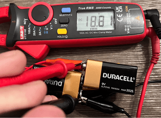
I am going to skip the parallel test and jump right into the series/parallel method. I don’t have 32 Eneloop batteries available to try this, but I do have some mix-and-match 9V batteries. A 9V battery, as implied by its name, supplies 9V. But here’s a little fun fact: In certain cases, 9V batteries are just six (6) AAAA batteries in series.

Depending on the battery, an alkaline AAA battery can store up to 1200mAh, or for lithium-ion/carbon-zinc batteries, up to 600mAh. I’m using alkaline batteries so we will safely say that each can produce ~1 amp of current. And as a public service announcement, DO NOT attempt to open a battery. Depending on the battery type, you can either get burnt by acid, the battery can catch on fire, or, in the case of lithium-ions, even explode.
Placing two (2) 9V batteries in serial should and does give me 18V. Testing this out confirms the configuration.
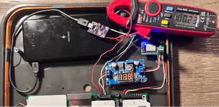
Placing two (2) 9V batteries in series gives me one (1) “large 18V battery”. By taking two (2) “large 18V batteries” (each large battery is a double 9V connected in a series connection), and placing them in a parallel connection, I keep the 18V but double the 1A. So, I took four (4) 9V at 1A batteries and made one (1) large 18V, 2A battery.
Now for the 2s2p configuration. I’ll take two (2) sets of 9V batteries (each set being two (2) 9V batteries in a 2s configuration) and connect their respective negative and positive terminals together.

Connecting this now to the MaxiProx, I’m again only getting <1 inch of range. So now it is time to check the current. My multimeter does not have a current jack, but it does have a clamp. The clamp is what you measure current with.
To measure current using the clamp, you first need to set it to what type of electricity you’re measuring: Alternating Current (AC), which is the kind you would find coming from a wall outlet in your house, or Direct Current (DC), which is what a battery supplies. Now, most multimeter clamps you find will only measure AC. The clamp I have, however, can measure both AC and DC.
Next, you need to pass the wire you’re looking to test through the clamp and make sure the clamp fully closes. It doesn't really matter if the wire is touching the side of the clamp, but it is important that the clamp is fully shut when taking a measurement. That said, to get the best measurement, it's recommended to have the wire passing through the center of the clamp and not touching the sides of the clamp. But again, it's much more important that the clamp is fully shut when taking the measurement. Additionally, when measuring DC with a clamp, it’s important that you:
A) Zero the clamp (aka hit the zero (0) button)
B) Try not to move the clamp at all after hitting zero (0)
Little side note: This whole zeroing process is only for DC measurements. For AC, no zeroing is needed. The reason for this is out-of-scope for this blog post. But for those following along at home, it’s important that this is done properly.
In checking the current, I was only reading 0.26A, ouch. I think some component is draining too much current.

Let’s try it with the USB battery pack.
Pinpointing the Problem
The MaxiProx is running idle at 0.23A. This does not seem right, so I decided to finally RTFM. The installation guide for the MaxiProx states that the recommended current supply should be 2.0A, has a peak current demand of 1.2A when in long-range mode, and the average consumption is .26A (260 milliamps). My test has confirmed that the idle current is running in range of what the installation manual is stating, so all is good there.

For fun, let’s test everything else out. First off, I have to disclose that we may not be able to identify the issue due to the unpredictability of electricity and how the circuits are built. Second, my handyman special multimeters will not give the most accurate readings for what we are trying to do but will give us a general idea of what is going on. Electrons moving in a circuit are moving very fast (fast enough that a single electron could go around the world in under 20 seconds), and the common multimeters can only take measurements at a fraction of that speed. So, with my multimeter, it's extremely likely that I’ll miss any current/voltage spikes. If you want to get a way more accurate reading, especially for electronics like this, you’ll need an oscilloscope. Oscilloscopes can take measurements at a vastly higher rate than a multimeter can. Plus, they can graphically show readings, which is useful for “seeing” what’s going on with those pesky little electrons. Think of an oscilloscope as one of those seismographs that show readings for earthquakes. An oscilloscope records in real time the activity, while a multimeter, like movie film, is a collection of pictures.
Now back to testing—let’s see how much current the buck module is pulling. From my test, 0.02A (20mA) is being utilized. Since I’m only taking a simple read of the buck module and not the whole MaxiProx/RFID setup, I’ll pull it out of the circuit and take some measurements directly from it, separate from anything else.

By adding the ESP RFID Tool, the current is now 0.06A (60mA). Subtract the 0.02A of the buck module, and the ESP RFID Tool runs off of 0.04A (40mA).

And now for checking the MaxiProx—we have to keep in mind that some devices draw a lot of power on startup. This phenomenon is referred to as inrush current and you need to be aware of items that require more current at startup to get components running before they idle at a lower current consumption rate. The main example here is a motor. Let’s see what the MaxiProx’s maximum startup current is. Again, an oscilloscope would be much better here at catching the startup current spike. But since I don’t own one, my multimeter will have to do.
The max current draw I saw showed 0.44A (440mA). Add this up with the buck module and ESP RFID Tool current demands, and we should get approximately 0.5A (500mA). Let's test that out.
Running the buck module, ESP RFID Tool, and the MaxiProx on startup was using a peak of 0.55A (548mA). That is nowhere near the peak 1.2A that the installation manual stated. Let’s test out some card reads.

Now here we can see that in this test at startup, the current jumps up to 0.436A. On card read, the current demand idles at 0.18A and ironically drops to 0.14A.
What I think is happening here is that the battery pack is just not capable of supplying the power needed, and I can’t get much further looking into this problem without better equipment like an oscilloscope. However, since this project is an introduction to hardware hacking, we won’t be getting into oscilloscopes.
But I do have a separate battery pack and a spare PD trigger, as my purchase was a two (2) pack, so let’s see what happens when I run the MaxiProx on one (1) battery pack and the buck module and ESP RFID Tool off another USB battery pack. I will configure the second PD trigger to draw 5V for the ESP RFID Tool and omit the buck module, as I no longer need that since the MaxiProx is now on its own battery pack.

And there it is, we have approximately 16 inches of range with this setup. I can’t for sure know what the exact issue is using the one (1) battery pack, but my hunch is that what the pack is capable of doing on paper just isn’t the same as what it can do in real life.
You’ve Got a Friend in Me
I won’t be able to fit two (2) battery packs in the MaxiProx with all the other components. Maybe I can find a USB battery pack that is more powerful? Time for this Buzz Lightyear to reach out to Andy’s toys for some help and once again run this by the TrustedSec Hardware Hacking team.
After bringing the Hardware Hacking team up to speed on where I was, Ryan Leese found a viable option. The form factor was perfect as it was less than ¾ inch and would allow the MaxiProx lid to close like I want it to. Also, this is a 100W power supply. Now we have not gone over watts yet, but in quick and simple terms, a watt is the measurement of the total power moving within a circuit. The equation for this is:

Term | Symbol | Unit of Measurement | Common Unit Abbreviation |
Power | P | Watts | W |
Voltage | E or V (they are interchangeable) | Volt (V) | V |
Current | I | Ampere (A) | A |
The battery pack Ryan recommended was the Baseus Laptop Power Bank that is rated for 100W. Each USB-C port is capable of an output of 20V at 5A. So by doing the wattage formula, (20V)(5A)=100W. Now, this is a $129.99 battery pack. When Ryan showed me this, I had to act fast as it could be all mine for the low, low price of $64.99!

So, off to ordering new parts, for the third time. This time I ordered the 100W battery pack as well as some shorter, 6-inch USB cables with one (1) end at a right angle since space in the MaxiProx will be cramped.
Part | Retailer | Cost |
Amazon | $64.99 | |
Amazon | $14.05 |

That poor Amazon delivery driver probably thought I was a package thief since I was waiting on the porch for the delivery. In fact, I was so excited that I didn’t even let him put it down on the doorstep. I just had to test this out. I was super excited to see what this workhorse could do and didn’t take the time to make it look pretty when I connected everything up.

And what do we have here? 22 inches?!?!

It is the greatest feeling in the world to get it right the first time.

Time to Hit the Wrap It Up Button

Before we wrap this up, I feel obligated to test out the amperage of our new donkey. The battery pack has an LCD screen that not only shows you the percentage of battery and approximate hours left, but it also tells you how many volts and amps are currently being used!
For reference, the first battery pack’s amperage test was as follows:
Test | Amperage |
Startup | 0.55A |
Idle | 0.18A |
Card Read | 0.14A |
The first battery pack was tested with the buck module and ESP RFID Tool in-line with the MaxiProx circuit. With the new setup, I have the MaxiProx plugged in to one (1) USB-C port and the ESP RFID Tool running from another.
Test | Amperage |
Startup | 0.80A |
Idle | 0.18A - 0.30A |
Card Read | 0.14A - 0.40A |
In part 1, we found out that the MaxiProx does a self-test and tunes the reader according to the power. I can only assume that the new battery pack is tunning correctly due to the input power having almost double.
So, what next? Join me in part 3 as we figure out how to take out the MaxiProx logic board to install a sound switch and then fit everything all nice and neat within the MaxiProx case!