Hardware Hacking: Plunder With a Bus Pirate

For this blog, I'm going to assume you have a Bus Pirate, you are able to access its terminal, and you are ready to use it—but what are you going to use it on? Grab a digital multimeter (you can get something for around $20 or less if you don't have one), some sort of IoT device that's been gathering dust in your closet, and time to choose your own adventure.
Finding the logic in it all...
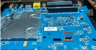
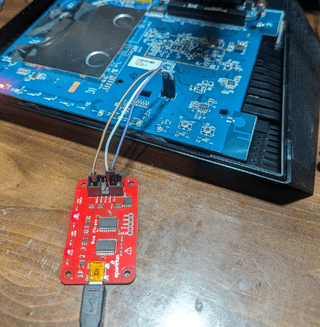
First, make sure the device is unpowered and the majority of the circuit board is exposed by removing the shell or, my personal favorite, cutting it open. Once the board is exposed, start looking around your circuit board for headers that are grouped together or a set of four through-holes grouped together. If there are four (4) headers in a row or a group of four (4) through-holes, there's a chance that the device can communicate over these pins using the UART protocol. If you are unsure what kind of device to open up, try a router (like the picture below). There’s a good chance you can find one at a second-hand store for next to nothing.
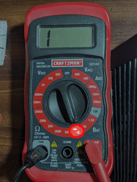
Set your multimeter to continuity test (i.e., the symbol that looks like a diode) to find ground. Depending on your multimeter, the display may vary for when you have continuity between probes. The easiest way to determine what to expect when you have continuity is to touch the metal probes together and see what happens. Mine beeps and displays a number if there is continuity, and infinity (i.e., left justified 1) if there isn't continuity between the probes. If your multimeter doesn’t have a continuity test, you can use an ohmmeter. The reading should be 0 or very close to 0 for continuity.
Since my test device has unpopulated headers, I'm going to hook one (1) of my probes to a pin and touch the other probe to something that's connected to the device’s ground. Keep moving the probe on the header to different pins until you find one that has continuity with ground. If you are uncertain of what ground is, some common culprits are USB shrouds, large metal areas such as the shroud that takes up 1/3 of this device's footprint, or screw holes that look like they have tin on them.
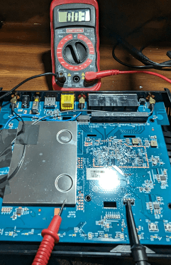
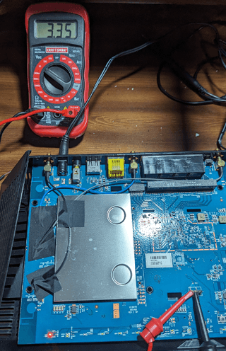
If you have found the pin connected to ground, one (1) of the other three (3) pins will supply voltage. Keep the negative (black) probe connected to ground and connect the positive probe (red) to a different pin and power the device on. If you see a constant voltage while it is booting and it is around 3.3 or 5 volts, this is most likely the UART’s power supply. If you see voltage but it appears to fluctuate rapidly, this is most likely the device's transmit pin. It is possible you may not find the transmit pin this way. The voltage change may happen so fast that you don't see it on your multimeter, or the device might not transmit anything until you send something to it.
If you happened to find the transmit pin, this leaves one (1) pin left in our group of four (4). With any luck, it will be the device's receive pin.
Now it’s time to connect the Bus Pirate. Connect the ground header to the ground on the Bus Pirate, the suspected transmit pin to the pin labeled MISO on the Bus Pirate, and the suspected receive pin to the Bus Pirate’s MOSI. If you are unsure of which pin is transmit and receive, connect the MOSI and MISO of the Bus Pirate to the device’s two pins that are not VCC and ground. The order doesn't matter here as we will make a guess as to which is transmit and receive. If we don't see any output through our testing, you can just swap the MOSI and MISO pins around and run through your testing again.
Let's throw some science at the wall and see what sticks
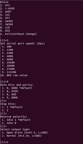
After connecting to the Bus Pirate's serial terminal, type m and hit enter to change the mode. My device has a UART interface, so I am going to enter 3 and select the baud rate for the device that we are testing. The baud rate varies from device to device. With this particular device, it is 115200 (option 9). If you don’t know the device's baud rate, that's OK, just try a common baud rate for now. After that, I try the default options except on the prompt for output type. For that, I'm choosing option 2.
Typing (0) into the Bus Pirate terminal will show the available macros for the current mode (UART in this case).
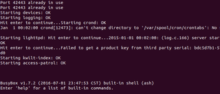
I typically pick option (1) or (3), to have an interactive shell once the device boots. If you haven't already, hit the power button on your device and see if any information is displayed.

With any luck, you'll see ASCII characters and recognizable words going across the screen. If you see a bunch of garbled text and unprintable characters, the ground pin on the header or the Bus Pirate could be loose, or one of the settings, most likely the baud rate, was incorrect during the UART configuration. At this point, you can try running through all of the baud rates to see if you end up getting readable ASCII text. If you do, then you have found the correct baud rate for your device.
If you don’t see any text or garbled data after pressing the power button, try hitting enter on your keyboard to see if there is a shell but nothing is output to the screen during boot until user input is detected. Another possibility is the transmit and receive pins are switched around. If you get to this point, you can swap the MOSI and MISO pins around and try running through all the baud rates again. Luckily, for this post, everything magically works.
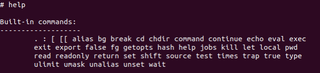
As suggested by the terminal, I attempt to use the help command, but it isn't very helpful.
At this point, we have a root shell on the device, so we have a lot of options at our disposal. For now, let's explore the file system a little further.
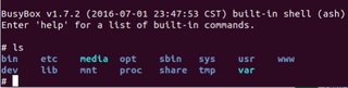
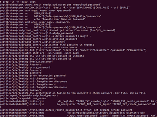
Using the stripped-down Linux shell, perform some recursive greps in various directories looking for key words like user or password. One (1) path that stuck out was the broken directory within /opt.
I like broken things, so let's explore some of those files.
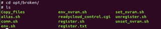
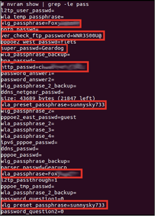
Looking at the Copy_files script, we find another command that is available to us: the nvram command. (It would have been nice if the help command told us this.)
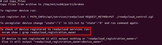
nvram stores information and persists after a reboot or power loss. Since this is a router, there's a good chance the Wi-Fi password is stored here. Grepping the output of nvram show, we find not only the Wi-Fi password but some other default passwords.
At this point, the world is your oyster. Choose your own adventure with this unknown file system and see what you can find. Happy hunting!