Hands On with Chip Off Non-Volatile Memory

Table of contents
1.1 Introduction - Why We're Here
Welcome to a deep dive into desoldering Non-Volatile storage chips! At the time of publishing, this is a recreation of my own first attempts at desoldering, and intended to encourage others into get into the world of hardware hacking. This post is split up into a few sections, but please feel free to skip around:
- End Result - The Dessert: A quick preview of where we want to get.
- Why & How: A brief description of how this came about, and how few skills were needed to accomplish this.
- Tools - Relatively Easy: A lengthy review of the primary tools used that may be new to readers.
- Step By Step - The Goods: A picture-heavy detailed guide on how to complete this process.
1.2 End Result - The Dessert
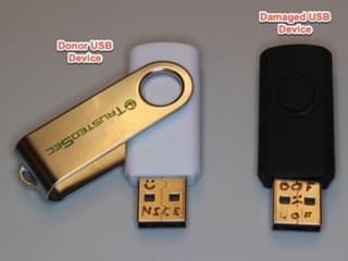
By the end of the blog, we should cover the removal and reinstallation of a physical memory chip from a broken USB storage device to a new donor module.
1.3 Why and How
A friend who works as a private investigator recently came to me with a challenge: could I recover data from a physically damaged USB drive? A suspect had crushed it in an attempt to destroy evidence. On close visual inspection of the drive, it appeared the memory module was intact. Up to this point in time, my own soldering experience was moderate at best. Simple projects, including headphone cable repairs, hobby through-hole component installs, fuse replacements, and some automotive wiring repairs. None of these were terribly technical or high-risk, but they did provide a reasonable introduction to soldering.
1.4 Tools - Relatively Easy
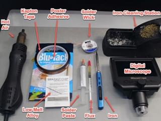
A relatively minimal set of tools was used during the memory module transplant. For learning purposes, we'll approach with the assumption that the basics are covered (such as an iron, flux-core solder, heat-safe worktop, rubbing alcohol, etc), and focus on the tools that were new to me. As a general best practice, be sure to read the manufacturer's instructions and cautions. Specific product usage here is not intended as a recommendation or endorsement.
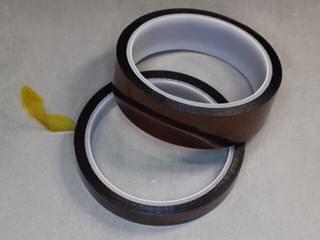
1.4.1 Kapton Tape
Kapton tape is a high-temperature tolerant tape. We can use it to secure board components and protect them from heat during soldering processes. It also can be used to help shield components from heat. It's important to note that the tape itself is temperature resistant, but the adhesive may soften with excessive heat exposure.
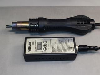
1.4.2 Hot Air
The hot-air tool might be new to the less experienced solder hobbyist. These tools come in a couple designs. This inexpensive one, priced around $30 at the time of the project, is essentially a miniature hair dryer. It allows a reasonably accurate temperature adjustment and generally vague airflow adjustment. It proved very helpful to bring the entire project up to the working temperature without much trouble. Larger hot air stations are also an option but not necessary for this project.
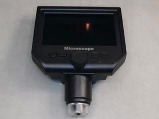
1.4.3 Digital Microscope
Another less common tool is the digital microscope. It's a multiuse tool that is surprisingly inexpensive for the value it adds. At the time of the project, it cost less than $40 and offered video recording as well as still pictures. I might replace it with an HDMI capable version in the future, which would provide a larger working image.
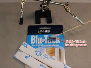
1.4.4 Poster Tack
Okay, so hear me out: Have you ever considered “Poster Tack”? It is incredibly easy to inadvertently bend or break component contacts when removing delicate soldered components. Professional shops use vacuum assisted lifting devices. Poster Tack adhesive is perfectly viable for our needs.
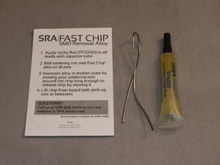
1.4.5 Desoldering Alloy
This is highly recommended, though somewhat unintuitive at first. Modern circuit boards use lead-free solder, which requires higher temperatures to melt. Excessive temperatures can damage the components. The desoldering alloy mixes with modern high-temp solder to significantly reduce the melting temperature to levels easily reached and maintained with hot air, reducing the impact to surrounding components. This is critical to safe removal of memory modules, which have many easily damaged pins affixed to the circuit board.
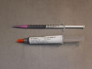
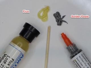
1.4.6 Solder Paste
Lastly, in lieu of conventional flux core solder, a soldering paste made its way into my toolbox. This is essentially microscopic beads of solder suspended in a flux paste and is designed to be used with hot air. I found that the consistency can be adjusted by adding conventional flux to tweak the viscosity to a desirable level, thus improving application.
1.5 Step by Step - The Goods
- Disassembly of Devices
- Removing Memory Modules
- Cleaning Module and Donor Board
- Install Memory Module on Donor Board
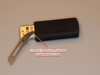
1.5.1 Disassembly of Devices
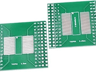
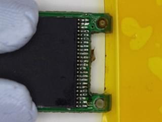
The best scenario for disassembly usually involves clearly visible screws and minimal snap-together parts. Unfortunately, that’s not the case here. Some gentle prying and probing revealed that the visible seams could be separated. Careful use of pry tools made quick work of the case. Before starting, both parts were marked to indicate “Donor” or “Recover”. Marks were reapplied multiple times throughout the entire process. On inspection, this NVM (Non-Volatile Memory) module is housed in a standard TSOP48 package.
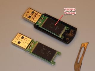
1.5.2 Removing Memory Modules
This specific surface mount device (SMD) has exposed pins, which are reasonably easy to desolder.
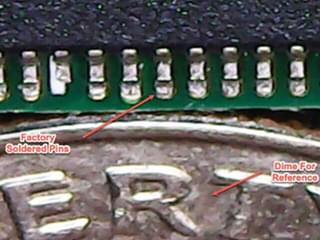
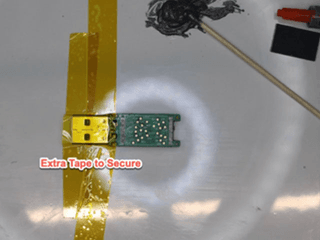
Two primary concerns when removing components include heat damage, and physical pin damage. While not always necessary, low-melt solder alloy significantly improves the success of desoldering. As a best practice, clean the work surface with alcohol that is 98% pure or better. I prefer to secure the workpiece to a 6" glazed ceramic tile using Kapton tape. I may occasionally add aluminum foil if there are especially heat-sensitive components in the way (Though fancy circuit board holding fixtures work as well).
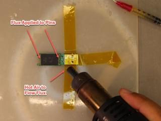
Start by applying liberal amounts of solder flux prior to any heat. Then, warm the entire board for 20 seconds with the hot-air flow set to 125°C. This step spreads the heat evenly across the board, helping to reduce thermal shock in the subsequent steps.
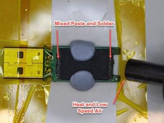
Finally, add low-melt alloy at 175°C with the hot air to soften the existing lead-free solder. Note that low-melt solder behaves somewhat differently than conventional solder. Depending on the formulation, it might require even lower temperatures for effective use. Additionally, low-melt solder may roll off of components like a liquid. Be careful to apply the low-melt solder only to the component to be removed. Use additional Kapton tape to mask off other components if needed.
Once the desoldering alloy is applied, the iron can be used to fully mix it with the factory solder at 300°C. If the entire area is warm, there should be several seconds of working time to remove the chip, so keep an eye for any movement. To safely remove the chip, use a semi rigid skewer with a pea-sized ball of Blu-Tac tac on the end. A wooden skewer or popsicle stick is fine. Attempt to lift the chip by sticking the Blu-Tac to the top of the chip. If the chip doesn't lift up easily, look closely for adequate desoldering alloy. When warm, the surface should shimmer and move like water.
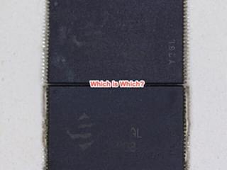
As soon as the chip is removed, label it and the board. Misidentifying the components at this point is easy. I usually move the broken board to another room or labeled container far away from my work area. Repeat the process for the donor board, and label or remove the unused memory module from the work area.
1.5.3 Cleaning Module and Donor Board
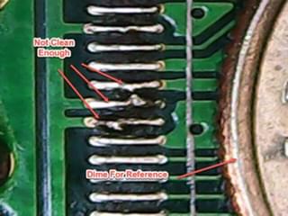
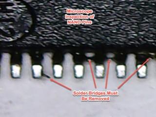
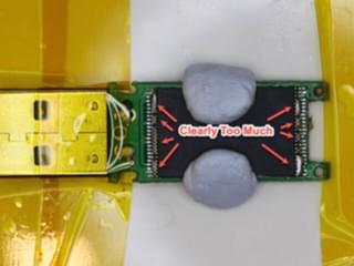
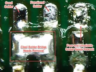
Preparing the donor board and original memory package may be an iterative process. Generally, this involves a repetitive cycle of applying alcohol, drying, then applying flux, applying new solder, and removing excess with a braided copper solder wick (if needed). It’s critical to be gentle with the circuit board pads, as rough cleaning can easily cause damage. While working on the board, the intention is to remove as much of the low-melt alloy as possible and to leave a very thin layer of solder. Solder is very likely to bridge between the memory module pins and can be very difficult to spot and remove. The microscope is very useful for verifying all surfaces are ready for reassembly.
1.5.4 Install Memory Module on Donor Board
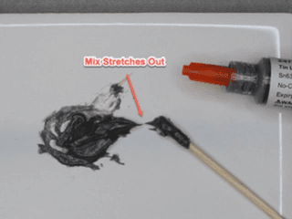
Solder paste can be easily applied with hot air and is surprisingly forgiving. Since the paste used here is well past the end of shelf life and hard to work with, we will mix a small amount of flux with the solder paste to adjust consistency to be thinner starting with a 50/50 mix. Keep in mind that brand new paste likely will not need any thinning. It’s critical to secure the circuit board with Kapton tape to the work surface during this process. We can apply a very light preparatory coating of flux on the circuit board pads, then carefully place the chip on the board. Align the pins carefully, then secure the chip with more Kapton tape or Blu-Tac. I prefer the Blu-Tac, as it is easier to adjust the final pin positioning. Kapton tape will hold more securely though.
Drape a thin string of the thinned paste/flux mix across the pins. This does not have to be perfect and will more than likely require another application of additional solder paste later. Apply a slow air flow and heat at temperature of 280°C until the paste melts and reduces, resulting in a shine on the paste. It’s important to remember this will likely not be sufficient to make all of the connections. It will, however, help set the chip in the proper position and allow better flow between pins and pads.
At this point, you should check the pins. It’s highly possible that some may have solder bridges, and some may not have sufficient solder. Use flux and braided wire to clean up excess spots, then add fresh solder paste. I used a very small syringe and tip to do this, but careful dabbing with a toothpick is also fine. This may take a few attempts to get satisfactory results.
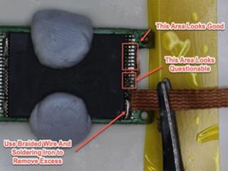
Inspect each joint under the microscope. Clean as necessary inspect again. There may be some solder bridges between pins, or possibly insufficient solder on pins. At this point, I fixed most of the issues with flux and a clean, fine tip on the soldering iron. Drag-Soldering is an iron technique where a freshly tinned iron is delicately dragged across all of the pins to quickly remove bridges and clean the joints. (See https://hakko.com.sg/blogs/tune-in-with-hakko/drag-soldering for additional information). It’s worth noting that this set of pictures was done with expired solder paste, which isn’t ideal for clean joints.
The final cleanup should be the last step (Fingers crossed). Start by wiping down the finished work with alcohol and then move to testing. Cautious individuals may consider testing for blue smoke via a small USB power pack, or an old expendable PC. Extremely precautious individuals might consider an opto-isolation USB module. In practice, the worst case is usually just a non-working USB storage device with soldering iron burns.
1.6 Wrap Up - No Blue Smoke Escape
We made it this far, which means we've got a functioning result. The filesystem is intact and we can copy from the device. While not data-recovery expert level work, this method sufficed when it counts. One obvious issue with the methodology here is reliance on donor parts. Another issue is the potential for other physical memory modules that aren’t suitable for soldering by hand. Next time, let's consider skipping the whole identical donor board and reading the memory directly. Inexpensive, generic new PCBs with varying pin pad layouts are available, as well as purpose built NVM interfaces.